您好,欢迎访问三七文档
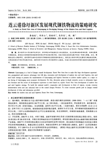
=VR•IRPI-3924-011706Figure1.TypicalApplication–notaSimplifiedCircuit(a)andOutputCharacteristicEnvelope(b).ProductHighlightsLowestSystemCostandAdvancedSafetyFeatures•Lowestcomponentcountswitcher•VerytightparametertolerancesusingproprietaryICtrimmingtechnologyandtransformerconstructiontechniquesenableClampless™designs–decreasescomponentcount/systemcostandincreasesefficiency•Meetsindustrystandardrequirementsforthermaloverloadprotection–eliminatesthethermalfuseusedwithlineartrans-formersoradditionalcomponentsinRCCdesigns•FrequencyjitteringgreatlyreducesEMI–enableslowcostinputfilterconfiguration•Meetshigh-voltagecreepagerequirementsbetweenDRAINandallotherpins,bothonthePCBandatthepackage•ProprietaryE-Shield™transformereliminatesYcapacitorSuperiorPerformanceoverLinearandRCC•Hystereticthermalshutdownprotection–automaticrecoveryimprovesfieldreliability•Universalinputrangeallowsworldwideoperation•Auto-restartreducesdeliveredpowerby85%duringshort-circuitandopenloopfaultconditions•SimpleON/OFFcontrol,noloopcompensationneeded•HighbandwidthprovidesfastturnonwithnoovershootandexcellenttransientloadresponseEcoSmart™–EnergyEfficiencyTechnology•Easilymeetsallglobalenergyefficiencyregulationswithnoaddedcomponents•No-loadconsumption30mWat230VACinput•ON/OFFcontrolprovidesconstantefficiencytoverylightloads–idealformandatoryCECregulationsApplications•Chargersforcell/cordlessphones,PDAs,powertools,MP3/portableaudiodevices,shaversetc.•StandbyandauxiliarysuppliesDescriptionSC1124switcherICscosteffectivelyreplaceallunregulatedisolatedlineartransformerbased(50/60Hz)powersuppliesupto3Woutputpower.Forworldwideoperation,asingleuniversalinputdesignreplacesmultiplelineartransformerbaseddesigns.Theself-biasedcircuitachievesanextremelylowno-loadconsumptionofunder30mW.Theinternaloscillatorfrequencyisjitteredtosignificantlyreducebothquasi-peakandaverageEMI,minimizingfiltercost.(a)(b)+DSFBBPDCOutputACINSC1124PI-6148-092310OutputPowerTableProduct4230VAC±15%85-265VACAdapter2OpenFrame3Adapter2OpenFrame3SC1124DG3W3W3W3WTable1.OutputPowerTable.Notes:1.OutputpowermaybelimitedbyspecificapplicationparametersincludingcoresizeandClamplessoperation(seeKeyApplicationConsiderations).2.Minimumcontinuouspowerinatypicalnon-ventilatedenclosedadaptermeasuredat50°Cambient.3.Minimumpracticalcontinuouspowerinanopenframedesignwithadequateheatsinking,measuredat50°Cambient.4.Packages:D:SO-8C.Forlead-freepackageoptions,seePartOrderingInformation.Rev.B11/102SC1124(SO-8C)BPFBD1248765SSSSFigure2.FunctionalBlockDiagram.PinFunctionalDescriptionDRAIN(D)Pin:ThepowerMOSFETdrainconnectionprovidesinternaloperatingcurrentforbothstartupandsteady-stateoperation.BYPASS(BP)Pin:A0.1µFexternalbypasscapacitorfortheinternallygenerated5.8Vsupplyisconnectedtothispin.FEEDBACK(FB)Pin:Duringnormaloperation,switchingofthepowerMOSFETiscontrolledbythispin.MOSFETswitchingisdisabledwhenacurrentgreaterthan70µAflowsintothispin.SOURCE(S)Pin:ThispinisthepowerMOSFETsourceconnection.ItisalsothegroundreferencefortheBYPASSandFEEDBACKpins.Figure3.PinConfiguration.PI-3958-092410CLOCKJITTERAUTO-RESTARTCOUNTERFAULTPRESENTOSCILLATOR5.8V4.85VSOURCE(S)SRQDCMAXADJBYPASS(BP)+-VILIMITLEADINGEDGEBLANKINGTHERMALSHUTDOWN+-DRAIN(D)BYPASSPINUNDERVOLTAGECURRENTLIMITCOMPARATORFEEDBACK(FB)OPENLOOPPULLDOWNQ6.3V1.69V-VTH0.8V+REGULATOR5.8VRESETRev.B11/103SC1124(pulsewidthmodulation)controllers,itusesasimpleON/OFFcontroltoregulatetheoutputvoltage.Thecontrollerconsistsofanoscillator,feedback(senseandlogic)circuit,5.8Vregulator,BYPASSpinundervoltagecircuit,over-temperatureprotection,frequencyjittering,currentlimitcircuit,andleadingedgeblanking.OscillatorThetypicaloscillatorfrequencyisinternallysettoanaverageof100kHz.Twosignalsaregeneratedfromtheoscillator:themaximumdutycyclesignal(DCMAX)andtheclocksignalthatindicatesthebeginningofeachswitchingcycle.Theoscillatorincorporatescircuitrythatintroducesasmallamountoffrequencyjitter,typically5%oftheswitchingfrequency,tominimizeEMI.Themodulationrateofthefrequencyjitterissetto1kHztooptimizeEMIreductionforbothaverageandquasi-peakemissions.Thefrequencyjitter,whichisproportionaltotheoscillatorfrequency,shouldbemeasuredwiththeoscilloscopetriggeredatthefallingedgeoftheDRAINvoltagewaveform.ThewaveforminFigure4illustratesthefrequencyjitter.TheoscillatorfrequencyisreducedwhentheFEEDBACKpinvoltageislessthan1.69Vasdescribedbelow.FeedbackInputCircuitThefeedbackinputcircuitattheFEEDBACKpinconsistsofalowimpedancesourcefolloweroutputsetat1.69V.Whenthecurrentdeliveredintothispinexceeds70µA,alowlogiclevel(disable)isgeneratedattheoutputofthefeedbackcircuit.Thisoutputissampledatthebeginningofeachcycleontherisingedgeoftheclocksignal.Ifhigh,thepowerMOSFETisturnedonforthatcycle(enabled),otherwisethepowerMOSFETremainsoff(disabled).Sincethes
 三七文档所有资源均是用户自行上传分享,仅供网友学习交流,未经上传用户书面授权,请勿作他用。
 扫描二维码
扫描二维码


 wangxlcnpc
本文标题:SC1124
链接地址:https://www.777doc.com/doc-6006531 .html